CAPACITORS
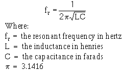
Unlike an ordinary, iron-core transformer, an air-core resonant transformer (like a Tesla coil) requires the frequency of the alternating current entering the primary coil to match the natural resonant frequency of the secondary coil. The resonant frequency is determined by the formula at right. The two circuits (primary and secondary), in a Tesla Coil's case, are quite different from one another. The secondary circuit has a massive inductance (due to the large coil size) and a tiny capacitance, therefore, to match the secondary circuit's frequency AND increase the output, the primary circuit must have a small inductance and a large capacitance. Since the self-capacitance of the primary coil by itself is practically non-existent, an additional, larger capacitance is required to put the two coils in tune. Enter the Tesla Coil's resonant capacitor.
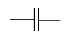
The capacitor, denoted by the symbol at right, is a energy storage device. A capacitor is formed by separating two or more oppositely-charged poles with a non-conductive substance, or "dielectric" (common examples include plastics, glass, oil, or air).
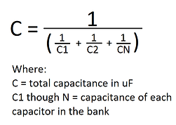
Since it is more expensive to buy a single, massive capacitor, many coilers choose to attach several capacitors together in different arrangements to, in essence, yield one giant capacitor. This arrangement is usually called an MMC (multiple mini capacitor) bank. Should you choose to do this, remember that capacitors in series added their voltages, but decrease the total capacitance (see the second formula). Capacitors in parallel add capacitances, but the voltage is equal to that of the lowest voltage capacitor in the bank.
When designing a Tesla Coil, the capacitor's voltage must be high enough to handle the massive voltage spikes produce during normal coil operation. The general rule is that the capacitor bank's rated DC voltage should be at least twice the transformer's peak voltage, which can be found be multiplying the rated output voltage of the transformer by 2.828. If this is not done, the capacitor bank will fail relatively quickly, since operating at or near the resonant frequency of the secondary causes voltages higher than those put out by the transformer to develop, thus damaging smaller-than-required capacitors. The easier (and safer) rule is to simply use triple the transformer's voltage. Since resonant voltage rise can also potentially damage the coil's transformer, many people choose to use a slightly larger-than-resonant capacitance. That way, the Tesla Coil will still function properly, but the slightly out-of-tune oscillations will prevent too much resonant voltage rise from occurring.
While there are many different types of capacitors, very few are actually suitable for use in a Tesla Coil. Here are some unqualified types:
-
Oil-filled capacitors (boil and explode)
-
Ceramic capacitors (overheat)
-
Polystyrene or polyester capacitors (arc internally and break down)
-
Polarized capacitors (i.e. ones with designated "+" or "-" terminals. These are usually oil-filled and explode)
Use of any of these capacitor types will result in their failure (sometimes, in oil-filled capacitors' case, explosively with lots of burning oil and fire). For use in a Tesla Coil, certain qualities are sought after in capacitors:
-
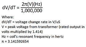
High dV/dT (voltage changing rate, usually listed in volts per microsecond, or V/uS) rating. The dV/dT rate of your coil can be found by using the formula at right. When capacitors are strung together in series, the dV/dT values (as well as their rated voltage) add to one another.
-
Polypropylene (PP) dielectrics are optimal
-
Self-healing ability. This comes in very handy, since even the best capacitor will eventually experience failure to some degree if used in a Tesla Coil.
-
Film or foil type
-
Pulse, AC, or high frequency rated
HOMEMADE CAPACITORS
In some cases (say, you're on a tight budget), you may not be able to buy capacitors. The alternative is to make your own capacitors. This is honestly not as hard as it sounds. The world's first capacitor was a glass jar filled with saltwater and surrounded with metal foil (called a Leyden jar). This basically gives you a relatively low capacitance (usually a little more than 0.7nF, or 0.0007uF, for a ordinary beer bottle) high voltage (over 25kV) capacitor. By putting several of these in parallel, you get a capacitor large enough to run a Tesla Coil. A favorite technique of coilers is to make a "bucket cap", in which you fit as many saltwater-filled bottles as possible into a 5-gallon bucket (paint, Home Depot, etc.) and fill the bucket up to the bottles' necks with saltwater. By connecting the saltwater on the inside of the bottles to one terminal and the saltwater filling the bucket to another, you get a relatively large capacitor (over fifteen average beer bottles will fit inside a 5-gallon bucket. With all of them in parallel, this giving you around a 10nF/25kV capacitor). To prevent the tremendously high voltages from jump from one saltwater terminal to the other, a small amount of non-conductive oil is usually added to the bottles and bucket. This forms an insulating layer (since oils float on water) that helps prevent arcing. Please note that bottle or bucket capacitors are not the most space-saving or effective option, since it would take five of more bottle capacitors in parallel to get a reasonable capacitance.
Another DIY capacitor option is to take non-conductive sheets (e.g. plastic bags, transparent projector sheets, or even clear packing tape), layer a few together (enough to handle your transformer's voltage, which can be done by zapping samples of the material and adding enough layers to prevent breakdown), and sandwich them between two metal foil strips. To save space, many people choose to roll their flexible capacitor up into a tube. This is actually closer to how modern capacitors are made, and will usually yield a smaller, higher-capacitance unit (sometimes a single cap can hold over 20nF, depending on the material and surface area of the electrodes). Click here for a great tutorial on this.


SPARK GAPS
Of all the essential components in a spark gap Tesla coil, the spark gap is by far one of the simplest. At its simplest, a spark gap is just what it sounds like: two conductors separated by a non-conductive medium that breaks down (sparks) under sufficient voltage. The medium is almost always air or some other gas, since solids and liquids tend to melt, boil, burn, or react in some way when exposed to an electrical discharge. The purpose of the spark gap is to act as a high speed switch that discharges the energy in the capacitor bank through the primary coil in as quick a pulse as possible. Adjusting the gap's spacing will dramatically alter the performance of a Tesla coil. The wider the gap is, the higher the voltage required from the capacitor. This roughly translates to more energy through the primary coil, and therefore longer arcs. This also means it could take longer to charge the capacitor (by a few hundredths of a second), and could reduce the BPS if the transformer doesn't supply a high enough current (the higher the current, the faster the capacitor bank will obtain a full charge).
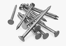
The first image is of a static spark gaps (static simply means there are no moving parts). As one can see, a static gap can be as simple as two nails placed next to one another. A slightly more complex design, known as the Richard Quick gap (seen at right), incorporates several smaller static gaps in series to achieve better quenching and cooler performance.
QUENCHING is a very important (and often not discussed) characteristic in a spark gap, and simply refers to how quickly the spark gap's discharge is extinguished. A big and very valid question from a beginner might be "why the heck is this even important?". Well, although a relatively small part of Tesla coil design, spark gap quenching can dramatically change a Tesla coil's arc length. A Tesla coil with poor quenching will tend to have more inconsistent discharges, shorter sparks, and more power drawn. Think of the spark gap as a switch. As long as the voltage/current are changing through the primary coil, a voltage will be induced. It only takes a short time for the capacitor to discharge itself and create a resonating current between itself and the primary coil. Once the capacitor is "empty", the switch (spark gap) will need to open so the energy will be directed into recharging the capacitor. If the gap is too small or the quenching is poor, the gap will remain ionized for longer, resulting in excess current draw (because the "switch" remains closed, or "on"), and lower firing voltages. Fortunately, quenching problems are easily fixed. The first easy fix is to blow or suck air across the gap. This effectively removes any ionized gas from the region, and decrease discharge "on" times. The second fix is to use a rotary gap.
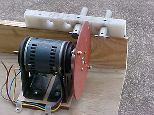
A rotary spark gap is a popular alternative to the static gap. Basically, a rotary gap is designed to rotate moving (or "flying") electrodes past two or more static electrodes at a high speed, essentially closing the "switch" each time they pass one another. This results more precisely-timed firings, highly efficient quenching, and an almost unlimited BPS range. A Tesla coil running with a rotary gap will also have arcs that produce a more specific tone of sound, while static gap coils tend to sound more like ragged hissing or crackling.
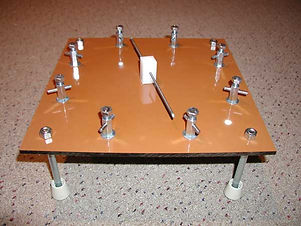
Rotary gaps come in two main flavors: propeller and disc. A disc-style gap (like the first two images at right) usually features an arrangement with several flying electrodes and two static electrodes. The flying electrodes can be electrically connected or not, depending on how one sets up the static electrodes. The first image of a disc-type rotary gap above shows an arrangement that requires an electrical connection between the flying electrodes, while the following image does not.
Disc rotary gaps, while popular, can be somewhat more challenging to build. Procuring an appropriate disc can be more difficult or costly than many desire, and balancing the disc correctly so it doesn't spin out of control can be a real pain. So what is a simpler alternative? Enter the propeller gap.
Propeller-style rotary spark gaps feature a setup with multiple static electrodes and single (or even double) conductive "propeller", as seen in the image at right. This design is far simpler to build and run, making it a popular choice for a rotary gap. The propeller electrode can be anything from long steel nails or bolts, to strips of thick copper wire, to full-blown tungsten welding rods. This overall versatility makes propeller gaps one of the best all-round choices for Tesla coil spark gaps.
Something to consider when building a spark gap of any type is what materials to use. To start, anything in close contact with the electrodes should be heat resistant, since the electrodes (especially those which are stationary) will get very hot very quickly during operation. Most materials may be used if:
-
The electrode is long enough to dissipate the heat itself
-
The electrode is thick enough to absorb most of the thermal energy
-
The electrode is held by an adequate metallic mount
For instance, in the propeller gap displayed here, one will notice the spinning electrode is held by nothing more than a small piece of plastic because the electrode is too long to cause it significant heating. And in the disc-type gap shown directly above it, the two stationary electrodes are being supported by large aluminum mounts, which are themselves supported by ordinary plastic and wood.
The electrodes themselves are made of metal, but which metal? It all depends on what the designer desires:
-
Steel is cheap and easy to find. It has a relatively high melting point, but may rust after a while. It's relatively poor thermal conductivity means most of the heat will stay at the "business end" of the electrode. This not only helps prevent the mount from burning up, but also helps ionize more difficult spark gaps (as a real-life example: in a 4kV coil I built, the gap would fire continuously if the electrodes were steel, but not if they were copper). While this may be a good thing, it also means the steel at the end may begin to melt and burn, sending off a shower of burning-hot sparks (I've had this experience in my medium-sized, 2kW triple MOT coil). This overheating can become more dangerous if the steel is galvanized, since the zinc coating will start to burn off, releasing zinc oxide smoke, which can be harmful if inhaled.
-
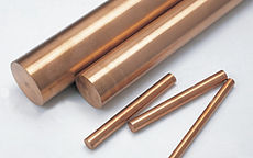
Copper is similar to steel in the way that it is cheap and easily obtainable. Unlike steel, it has a high thermal conductivity, and is a less reactive metal, so it is less likely to begin melting and will not emit unwanted metal sparks or metal oxide fumes.
-
Brass is another popular metal for use as spark gap electrodes, for similar reasons as steel and copper. It's melting point, however, is noticeably lower, which may become an issue in larger coils. Additionally, since brass is an alloy of zinc and copper, zinc oxide fumes may be released upon excessive heating. Unlike galvanized steels, though, this zinc isn't just surface-depth, and may be release throughout the entire life of the electrode.
-
Tungsten is generally the metal of choice in Tesla coil spark gaps. It has the highest melting point of any metal, and is available as welding rods for arc welders. Unfortunately, it is somewhat expensive and harder to find. It is also very difficult to machine or cut (even diamond-tipped blades have trouble), due to it's high density, and is somewhat brittle.